How Does LiteTouch Work? A Technical Breakdown of the System
Want the full backstory first? See What Happened to LiteTouch? for the company’s history from its founding in the late 1970s through its discontinuation in 2015. If you already know you need to replace one, our LiteTouch Replacement Guide covers the process end to end.
If you’ve got a LiteTouch panel in your house and you’re trying to understand what’s actually happening behind the keypads before deciding what to do about it, here’s how the system is built, piece by piece.
The Core Architecture: Panelized and Hardwired
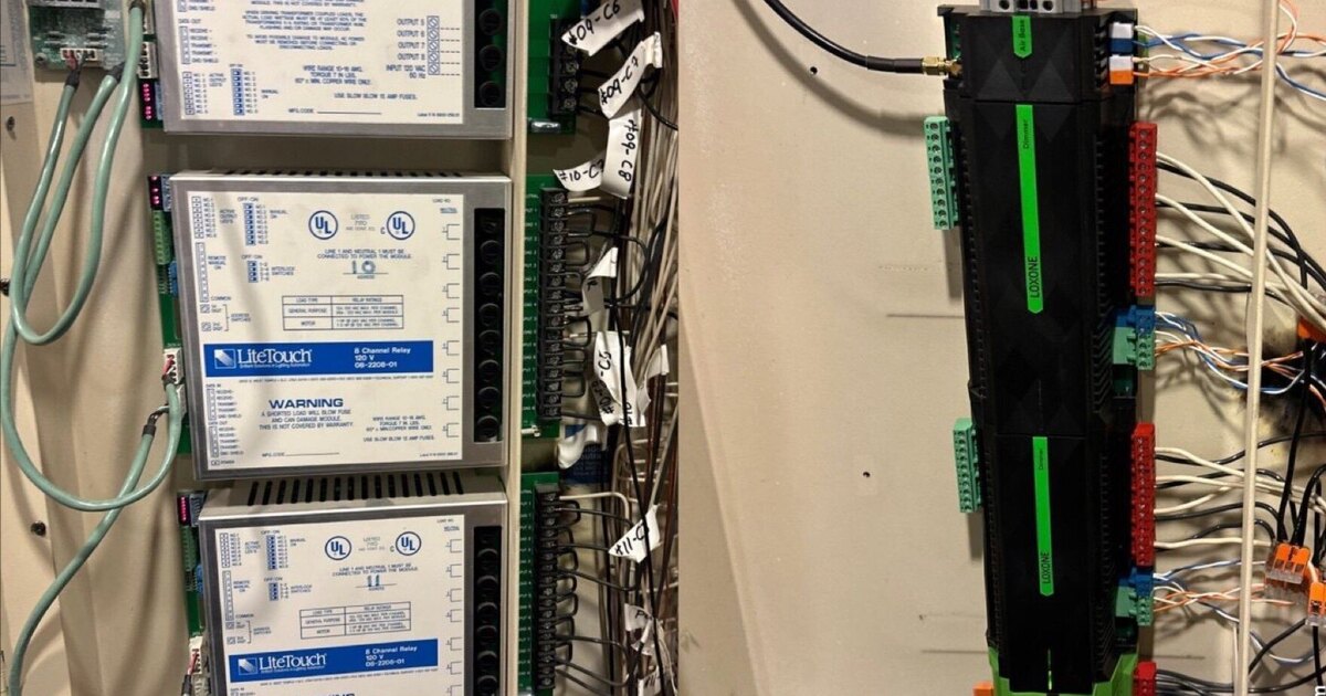
LiteTouch is what’s called a panelized lighting control system. That means the components that actually do the electrical switching — the dimmer and relay modules — aren’t distributed at each light fixture or behind each wall switch the way a standard home is wired. Instead, they’re centralized in one or more enclosures, typically located near the home’s electrical panel or in a dedicated equipment closet.
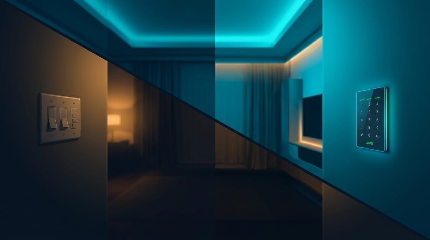
Every keypad in the house is wired back to this central location on low-voltage control cable. When you press a button, you’re not switching a light directly — you’re sending a signal back to the panel, where the actual switching happens. This is a fundamentally different wiring topology from a standard toggle switch, and it’s the reason LiteTouch systems can do things a normal switch can’t: multiple keypads controlling the same load, scenes that adjust several circuits from one button press, and centralized programming changes without rewiring anything.
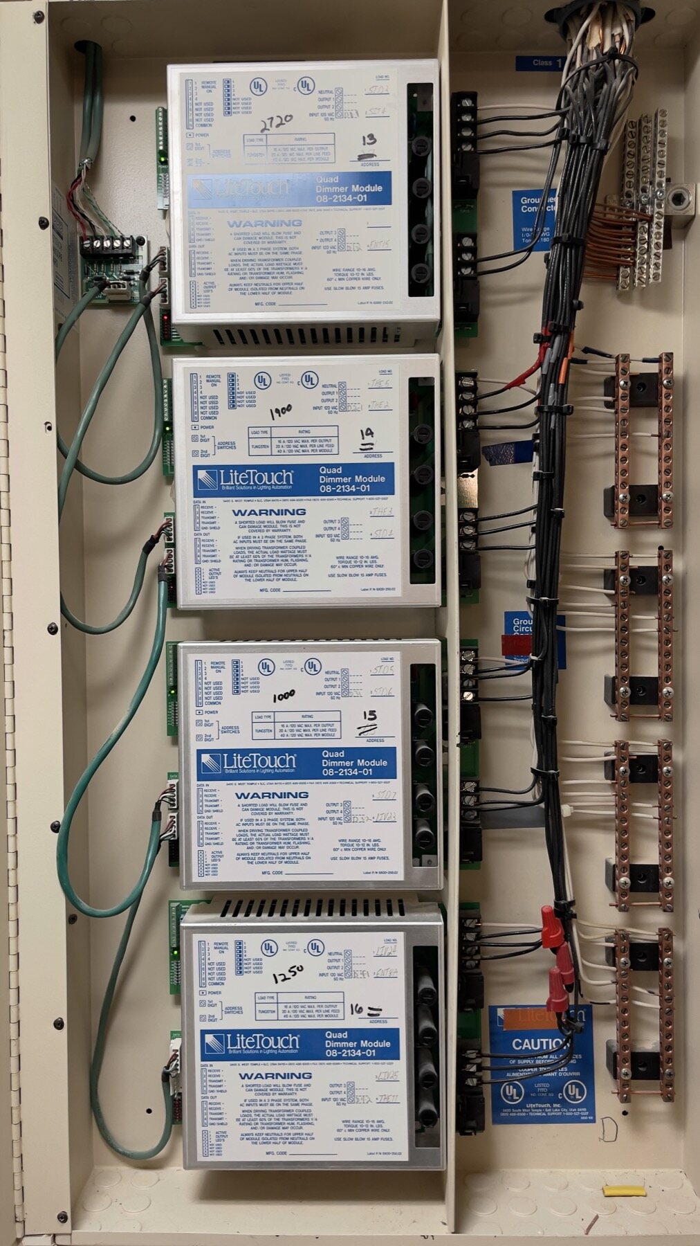
Four Quad Dimmer Modules in one enclosure. The handwritten numbers are the installer’s load calculations (2720W, 1900W, 1000W, 1250W) and the module addresses (13 through 16) — the only record of what each output feeds.
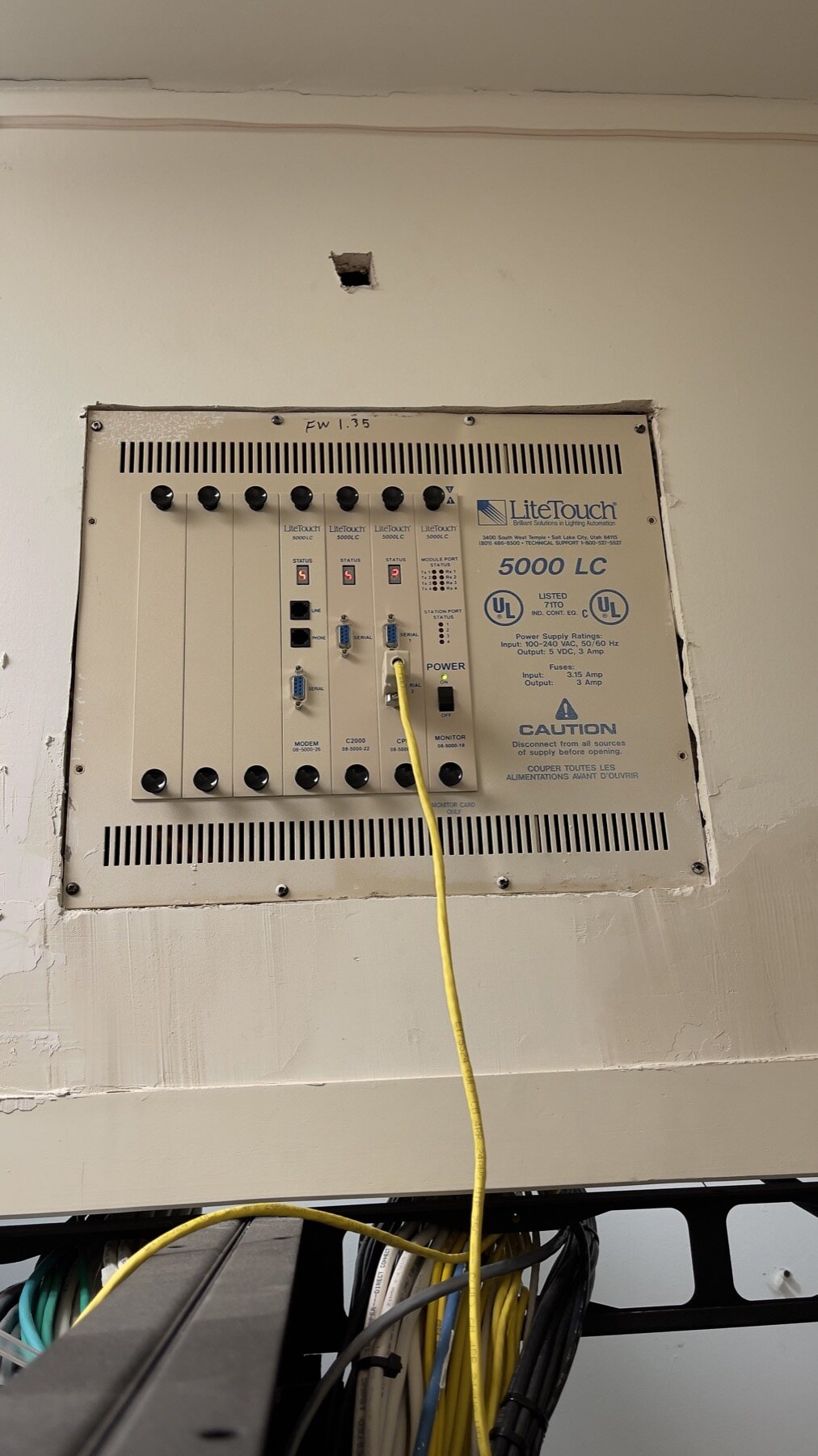
The 5000 LC Central Control Unit — the brain. Every keypad press in the house routes through these cards before a single light changes state.
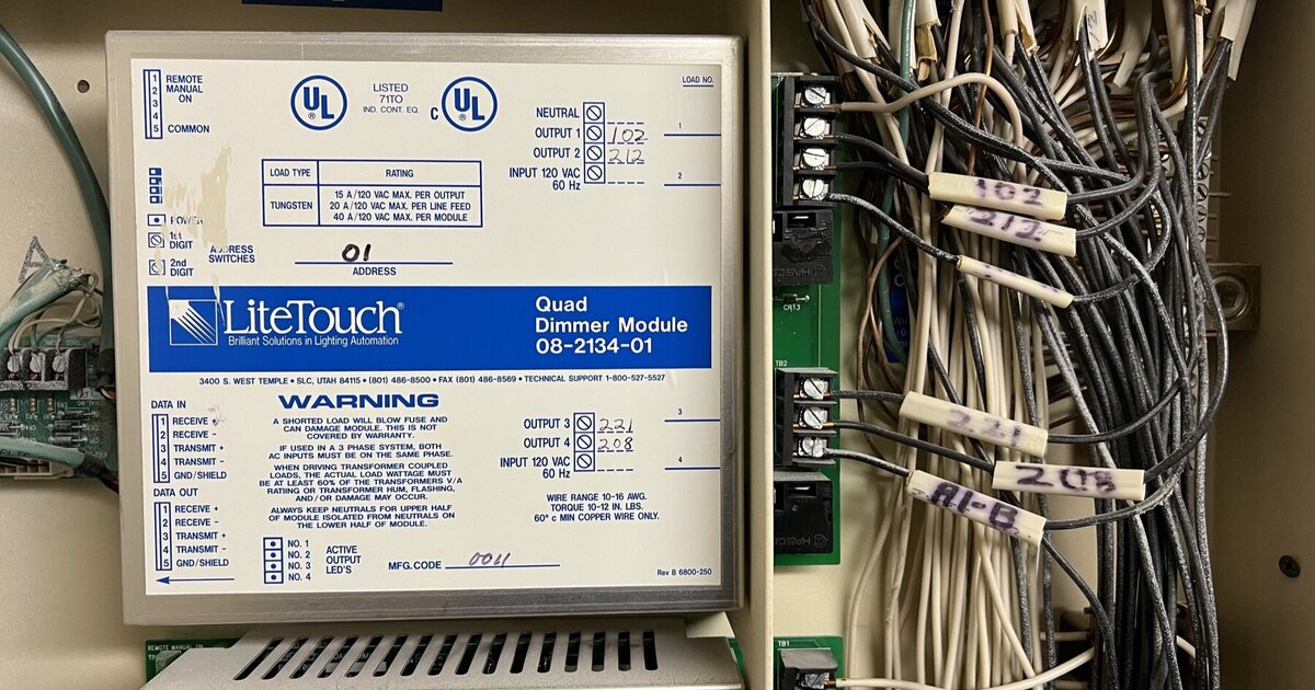
The other half of the system: Quad Dimmer Modules (part 08-2134-01) stacked in the enclosure, each output wired to a hand-labelled circuit. The keypad sends a signal; these modules switch the actual load.
The Central Control Unit (CCU): The Brain
At the center of every LiteTouch installation is the Central Control Unit, or CCU. Every keypad button press gets sent to the CCU first. The CCU holds the system’s programming — which button on which keypad triggers which action — and it’s responsible for translating a simple button press into the correct commands sent out to the dimmer, relay, and motor modules.
This centralized-brain design has one practical upside that’s worth noting even now, more than a decade after discontinuation: because all the logic lives in the CCU rather than being distributed across individual switches, a working CCU with intact programming can keep a system running reliably for a long time, with no software updates and no internet connection required. It’s also the single point of failure — if the CCU loses its programming or fails outright, the whole system’s logic goes with it, and there’s no cloud backup to restore from. A CCU showing a locked-up status display is one of the most common faults we walk homeowners through in our troubleshooting guide, including the reset step to try before assuming the worst.
Keypads: 1 to 9 Buttons, Wired Back to the CCU
LiteTouch keypads came in a range of sizes, from single-button stations up to 9-button units, chosen based on how much a given wall location needed to control. A hallway might use a simple 2-button keypad for on/off. A great room or a primary scene-control location near a main entry might use a 6- or 9-button keypad to trigger a full set of lighting scenes — “evening,” “movie,” “entertaining,” “all off” — from a single press.
Each keypad is wired back to the CCU on low-voltage cable. The typical wiring standard was 3-conductor cable, with many installers running 4-conductor instead so there’d be a spare conductor available if one in the run ever failed — a practical hedge against having to pull new wire through finished walls years later. This cable was commonly left untwisted and unshielded, which was standard practice for the era and application. It matters today because it’s a real point of difference from most contemporary low-voltage control buses, which are generally engineered around twisted, shielded pairs to reject electrical interference more reliably. Anyone evaluating what can be reused from an existing LiteTouch installation needs to look at this wiring specifically, not just assume it will work with a different platform’s bus.
Control Modules: Dimmer, Relay, and Motor
Inside the panel enclosure, the actual switching happens through control modules. LiteTouch used three types:
- Dimmer modules control the intensity of a connected lighting circuit, letting it fade smoothly to a preset level instead of only switching fully on or off. These were used for incandescent and halogen loads, which is what the vast majority of LiteTouch-era installations were built around.
- Relay modules are simpler on/off switches. They’re used for non-dimmable lighting loads and other switched circuits — some installations used relay modules for small motors, fans, or other equipment beyond lighting.
- Motor modules control motorized loads directly, most commonly window shades or projection screens in home theater rooms.
Each module type handles one job well, and a given panel enclosure typically housed a mix of all three depending on what the home needed controlled. This modularity was actually one of LiteTouch’s stronger design decisions — a failed dimmer module theoretically could be swapped without touching the rest of the system, though in practice, sourcing a replacement module today is close to impossible since none have been manufactured since the 2015 discontinuation.
LiteWare: How the System Got Programmed
Everything about how a LiteTouch system behaves — which button does what, how a scene is built, what schedule (if any) is running — was configured through LiteWare, the manufacturer’s dedicated programming software. An installer connected a computer running LiteWare to the CCU over a local cable connection and pushed configuration changes directly to the panel.
There was no app, no cloud sync, and no remote access — none of that existed as a category when LiteWare was built. Making a programming change meant physically connecting to the CCU on-site. This is worth understanding because it explains why reprogramming a LiteTouch system today is so difficult: the software itself is no longer distributed, the cable connection method is dated, and the number of technicians who still have both the software and the working knowledge to use it shrinks every year.
Putting It Together: A Simple Signal Path
The full signal path for a single button press looks like this: you press a button on a keypad → the signal travels over low-voltage 3-conductor (or 4-conductor) wiring back to the CCU → the CCU checks its programming to see what that button is supposed to do → the CCU sends the corresponding command out to the relevant dimmer, relay, or motor module → the module switches or dims the connected load.
It’s a straightforward, reliable architecture, which is a large part of why so many LiteTouch systems installed decades ago are still physically functioning today. The limitation isn’t the core electrical design — it’s that the ecosystem around it (parts, software, trained installers) stopped being maintained in 2015, and every year that passes makes keeping a system running, or modifying it, harder than the year before.
What This Means If You’re Considering Replacement
Understanding the architecture matters when you’re evaluating replacement options, because it directly determines what can be reused. The line-voltage wiring running from the panel’s dimmer and relay modules out to your light fixtures is standard electrical wiring, and that’s generally reusable with most modern platforms. The low-voltage keypad wiring is the piece that needs a closer look, given its typical unshielded, untwisted construction — whether it’s suitable for reuse depends on the specific replacement platform and gets assessed wire run by wire run.
Our LiteTouch Replacement Guide covers what a modern migration actually involves in detail — what’s reused, what’s replaced, typical cost ranges, and the phase-by-phase process. If you want a rough estimate specific to your home’s size and keypad count, our LiteTouch replacement cost calculator is a faster starting point.
A Note From Us
We hold Texas security license #B-29733501 and have been a Loxone Partner since 2015 (Platinum today), working on lighting control systems — including a fair number of LiteTouch installations — across Spring and the greater Houston area. If you want someone to look at your specific panel and tell you honestly what state it’s in, book the $450 diagnostic.
Ready to discuss your smart home project?
Book a free consultation — we'll discuss your goals and outline options.
Book a Free ConsultationShare this article

Founder & Mechatronics Engineer
Daniel Lopez founded Grizzly Tec in 2012 and has designed and installed 1,000+ projects (audio, video, networking, security and automation), including 50+ LOXONE projects. A mechatronics engineer by training, he holds a Texas security license (B-29733501) and has been a LOXONE Partner since 2015 and a Platinum Partner today.